LW26-20A/2 Isolating for Water Pump
You can purchase Lixin LW26-20A/2 insulation for Water Pump with confidence. The LW26 series of rotary switches, such as 3 Position On-off-On Rotary Cam Switch, are intended for use in an electric system operating at 50 Hz alternating current. They can handle operating voltages of up to 440V AC and DC voltages up to 240 V, with a rated current capacity of 315A. These switches provide reliable control for occasional manual connection or disconnection, allowing them to adapt to a wide variety of applications. Moreover, they allow direct control of three-phase asynchronous motors, fulfilling both primary command control and circuit measurement requirements.
Send Inquiry
Product Description
As a specialized manufacturer, we are willing to supply you with Lixin LW26-20A/2 Insulation for Water Pump. The 2 Position On-off-On Rotary Cam Switch, tailored for applications that require speed regulation, provides increased operational versatility. In the LW26 series, these switches serve a variety of functions, such as circuit control switches, test equipment switches, motor control switches, and master control switches, as well as welding machines.
LW26 Series ensures that the rules of the industry are adhered to. Available in a variety of sizes ranging from 10A to 315A, these switches are characterized by compact design, careful selection of materials, and strong insulation performance. Their flexible operation, together with security features such as finger protection, guarantee reliable performance in a wide range of environments.
The LW26 Series is an innovative solution that provides an ideal upgrade option, which can be used to replace older switches and switch switches in imported devices.
Lixin 2 Position On-off-On Rotary Cam Switch Combination of operation mode and actuator position
|
Controls way |
trait designation |
Actuator position |
|||
|
Self-replicating type |
A |
0°30° |
0-45° |
0°-60° |
|
|
B |
30°-0°30° |
45°0°-45° |
60°0°-60° |
||
|
X |
60-30=0°30-60° |
||||
|
Locating type |
C |
0°30° |
0°45° |
0°60° |
|
|
D |
30°0°30° |
45°0°45° |
60°0°60° |
||
|
E |
30°0°30°60° |
45°0°45°90° |
60°0*60*120° |
||
|
F |
60°30°0°30°60° |
90°45°0°45°90° |
60°0°60°120°180° |
||
|
G |
60°30°0°30°60°90° |
90°45°0°45°90°135° |
120°60°0°60°120°180° |
||
|
H |
90°60°30°0°30°60°90° |
135°90°45°0°45°90°135° |
|||
|
90°60°30°0°30°60°90°120° |
135°90°45°0°45°90°135°180° |
||||
|
J |
120°90°60°30°0°30°60°90°120° |
||||
|
K |
120°90°60°30°0°30°60°90°120°150° |
||||
|
L |
150°120°90°60°30°0°30°60°90°120°150° |
||||
|
M |
150°120°90°60°30°0°30°60°90°120°150°180° |
||||
|
N |
45° 45° |
30°30° |
|||
|
P |
90°0°90 |
||||
|
T |
0*90° |
||||
|
V |
90°0° |
||||
|
R |
270°0°90°180° |
||||
|
orientation Self-replicating type |
Q |
30°0°-30° |
45-0°45° |
||
|
S |
30°-0°60° |
90°0°-45 |
|||
|
W |
90-45°0°45-90° |
||||
|
Z |
120°-90°0⁰-30° |
135°-90°0⁶-45° |
Lixin 2 Position On-off-On Rotary Cam Switch Type specification
|
Type specification |
LW26-10 LW26-10G LW26-10X |
LW26-20 LW26-20X LW26-20C |
LW26-25 |
LW26-32 LW26-32F |
LW26-40 LW26-40F |
LW26-63 LW26-63F |
LW26-125 |
LW26-160 |
LW26-250 |
LW26-315 |
|
Ui V |
660/690 |
660 |
660 |
660 |
660 |
660 |
660 |
660 |
660 |
660 |
|
Ith A |
10 |
20 |
25 |
32 |
40 |
63 |
125 |
160 |
250 |
315 |
|
Ue V |
240440 |
24110240440 |
24110240440 |
240440 |
240440 |
240440 |
240440 |
240 440 |
240440 |
240440 |
|
le |
||||||||||
|
AC-21A AC-22A A |
1010 |
20 20 |
25 25 |
32 32 |
63 63 |
100 100 |
150 150 |
200200 |
315 315 |
|
|
AC-23A A |
7.57.5 |
15 15 |
22 22 |
30 30 |
37 37 |
57 57 |
90 90 |
135 135 |
265 265 |
|
|
AC-3 A |
5.55.5 |
11 11 |
15 15 |
22 22 |
30 30 |
36 36 |
75 75 |
95 95 |
110 110 |
|
|
AC-4 A |
1.751.75 |
3.5 3.5 |
6.5 6.5 |
11 11 |
15 15 |
30 30 |
55 55 |
95 95 |
||
|
AC-15 A |
2.51.5 |
5 4 |
8 5 |
14 6 |
||||||
|
DC-13 A |
12 0.40.4 |
20 0.5 0.5 |
||||||||
|
Rated control power P |
||||||||||
|
AC-23A KW |
1.8 3 |
3.7/2.5 7.5/3.7 |
5.5/311/5.5 |
75/415/75 |
185/918.5/9 |
15/1030/18.5 |
30/1545/22 |
37/2275/37 |
75/37132/55 |
|
|
AC-2 KW |
2.53.7 |
4 7.5 |
5.5 11 |
75 15 |
185 30 |
30 45 |
37 55 |
55 95 |
||
|
AC-3 KW |
1.52.2 |
3/22 5.5/3 |
4/3 7.5/3.7 |
55/411/5.5 |
15/7.515/7.5 |
11/618.5/11 |
15/7.530/13 |
22/1137/18.5 |
37/2255/30 |
|
|
AC-4 KW |
0.370.55 |
0.55/0.751.5/1.5 |
1.5/1.13/2.2 |
27/1.555/3 |
55/2475/4 |
6/312/5.5 |
10/415/7.5 |
15/7.525/11 |
Lixin 2 Position On-off-On Rotary Cam Switch Normal working condition
1. The ambient air temperature must remain within the range of -25°C to +40°C, with a 24-hour average not exceeding 25°C.
2. The lower limit of the ambient air temperature should not drop below -25°C.
3. Installation locations should not exceed an altitude of 2000m above sea level.
4. At maximum temperature conditions of +40°C, the relative humidity of the air should not exceed 50%. Higher relative humidity levels may be permissible at lower temperatures, such as reaching 90% at 20°C. Special precautions must be taken to mitigate condensation resulting from temperature fluctuations.
Lixin 2 Position On-off-On Rotary Cam Switch Installation condition:
1. The switch is installed in an environment with pollution level 3 conditions.
2. Installation should be carried out according to the instructions provided by our factory.
Lixin 2 Position On-off-On Rotary Cam Switch sort:
1 Divided by use
(1) Switch for main circuit conversion;
(2) Transfer switch for direct control of the motor; (3) Transfer switch for master control and measurement.
2 According to the operation mode
(1) Positioning type;
(2) self-replicating type;
(3) Positioning self-replicating type.
3 According to the contact system
(1) The positioning type switch has 1 to 12 sections (only 8 sections for 63A and above switches);
(2) The self-restoring type transfer switch has 1 to 3 sections (LW26-20; Verses 1 to 8)
(3) The transfer switch for direct control of the motor mainly has 1 to 6 sections.
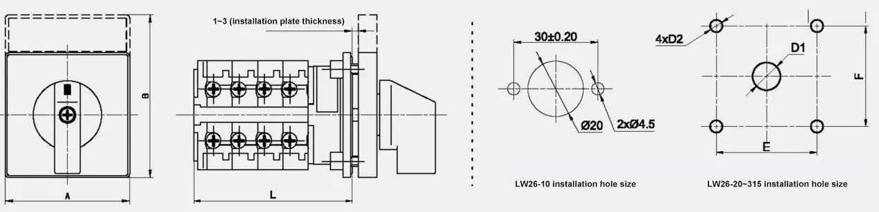
Lixin 3 Position On-off-On Rotary Cam Switch Overall dimensions and mounting dimensions:
Hot Tags: LW26-20A/2 Isolating for Water Pump, China, Manufacturer, Supplier, Factory, Wholesale, Customized, Cheap, Quality, Brands
Related Category
Send Inquiry
Please Feel free to give your inquiry in the form below. We will reply you in 24 hours.