LW26 Rotary Switch
LW26 series transfer switch is a multi-functional electrical control device, its design meets the requirements of GB/T 14048.3,GB/T 14048.5 and other national standards, mainly suitable for AC 50Hz, rated operating voltage 440V and below or DC voltage 240V and below industrial electrical environment. The modular design of the product has a wide range of rated current coverage up to 315A, which is especially suitable for circuit control scenarios requiring manual infrequent operation. Its core functions include circuit on-off control, electrical parameter measurement and system conversion, which can be widely used in power distribution system control, electrical equipment debugging, power circuit switching and other fields, especially suitable for industrial sites with high requirements for operational safety and equipment reliability.
Send Inquiry
Product Description
As an electrical control solution for multi-scenario applications, the LW26 series transfer switches show their unique value in many fields. In terms of motor control, it can directly control the start, stop and turn of three-phase asynchronous motor to meet the control needs of machine tools, conveyor belts and other equipment; As a master controller, it can cooperate with PLC system to realize complex logic control. In the field of testing, its precise contact system can meet the measurement requirements of various electrical parameters. The product especially strengthens the adaptability in harsh working conditions, adopts silver alloy contact and arc extinguishing chamber design, can withstand the high frequency current impact of welding machine and other equipment. With IP65 protection grade, high temperature engineering plastic housing and humanized operation handle design, this series of switches has been successfully used in power systems, rail transit, building distribution, machinery manufacturing and other industries, becoming a trusted choice of electrical components in the field of industrial control.
Lixin LW26 Series Rotary Cam Switch Combination of operation mode and actuator position
|
Controls way |
trait designation |
Actuator position |
|||
|
Self-replicating type |
A |
0°30° |
0-45° |
0°-60° |
|
|
B |
30°-0°30° |
45°0°-45° |
60°0°-60° |
||
|
X |
60-30=0°30-60° |
||||
|
Locating type |
C |
0°30° |
0°45° |
0°60° |
|
|
D |
30°0°30° |
45°0°45° |
60°0°60° |
||
|
E |
30°0°30°60° |
45°0°45°90° |
60°0*60*120° |
||
|
F |
60°30°0°30°60° |
90°45°0°45°90° |
60°0°60°120°180° |
||
|
G |
60°30°0°30°60°90° |
90°45°0°45°90°135° |
120°60°0°60°120°180° |
||
|
H |
90°60°30°0°30°60°90° |
135°90°45°0°45°90°135° |
|||
|
90°60°30°0°30°60°90°120° |
135°90°45°0°45°90°135°180° |
||||
|
J |
120°90°60°30°0°30°60°90°120° |
||||
|
K |
120°90°60°30°0°30°60°90°120°150° |
||||
|
L |
150°120°90°60°30°0°30°60°90°120°150° |
||||
|
M |
150°120°90°60°30°0°30°60°90°120°150°180° |
||||
|
N |
45° 45° |
30°30° |
|||
|
P |
90°0°90 |
||||
|
T |
0*90° |
||||
|
V |
90°0° |
||||
|
R |
270°0°90°180° |
||||
|
orientation Self-replicating type |
Q |
30°0°-30° |
45-0°45° |
||
|
S |
30°-0°60° |
90°0°-45 |
|||
|
W |
90-45°0°45-90° |
||||
|
Z |
120°-90°0⁰-30° |
135°-90°0⁶-45° |
Lixin LW26 Series Rotary Cam Switch Type specification
|
Type specification |
LW26-10 LW26-10G LW26-10X |
LW26-20 LW26-20X LW26-20C |
LW26-25 |
LW26-32 LW26-32F |
LW26-40 LW26-40F |
LW26-63 LW26-63F |
LW26-125 |
LW26-160 |
LW26-250 |
LW26-315 |
|
Ui V |
660/690 |
660 |
660 |
660 |
660 |
660 |
660 |
660 |
660 |
660 |
|
Ith A |
10 |
20 |
25 |
32 |
40 |
63 |
125 |
160 |
250 |
315 |
|
Ue V |
240440 |
24110240440 |
24110240440 |
240440 |
240440 |
240440 |
240440 |
240 440 |
240440 |
240440 |
|
le |
||||||||||
|
AC-21A AC-22A A |
1010 |
20 20 |
25 25 |
32 32 |
63 63 |
100 100 |
150 150 |
200200 |
315 315 |
|
|
AC-23A A |
7.57.5 |
15 15 |
22 22 |
30 30 |
37 37 |
57 57 |
90 90 |
135 135 |
265 265 |
|
|
AC-3 A |
5.55.5 |
11 11 |
15 15 |
22 22 |
30 30 |
36 36 |
75 75 |
95 95 |
110 110 |
|
|
AC-4 A |
1.751.75 |
3.5 3.5 |
6.5 6.5 |
11 11 |
15 15 |
30 30 |
55 55 |
95 95 |
||
|
AC-15 A |
2.51.5 |
5 4 |
8 5 |
14 6 |
||||||
|
DC-13 A |
12 0.40.4 |
20 0.5 0.5 |
||||||||
|
Rated control power P |
||||||||||
|
AC-23A KW |
1.8 3 |
3.7/2.5 7.5/3.7 |
5.5/311/5.5 |
75/415/75 |
185/918.5/9 |
15/1030/18.5 |
30/1545/22 |
37/2275/37 |
75/37132/55 |
|
|
AC-2 KW |
2.53.7 |
4 7.5 |
5.5 11 |
75 15 |
185 30 |
30 45 |
37 55 |
55 95 |
||
|
AC-3 KW |
1.52.2 |
3/22 5.5/3 |
4/3 7.5/3.7 |
55/411/5.5 |
15/7.515/7.5 |
11/618.5/11 |
15/7.530/13 |
22/1137/18.5 |
37/2255/30 |
|
|
AC-4 KW |
0.370.55 |
0.55/0.751.5/1.5 |
1.5/1.13/2.2 |
27/1.555/3 |
55/2475/4 |
6/312/5.5 |
10/415/7.5 |
15/7.525/11 |
Lixin LW26 Series Rotary Cam Switch Normal working condition
1. The ambient air temperature must remain within the range of -25°C to +40°C, with a 24-hour average not exceeding 25°C.
2. The lower limit of the ambient air temperature should not drop below -25°C.
3. Installation locations should not exceed an altitude of 2000m above sea level.
4. At maximum temperature conditions of +40°C, the relative humidity of the air should not exceed 50%. Higher relative humidity levels may be permissible at lower temperatures, such as reaching 90% at 20°C. Special precautions must be taken to mitigate condensation resulting from temperature fluctuations.
Lixin LW26 Series Rotary Cam Switch Installation condition:
1. The switch is installed in an environment with pollution level 3 conditions.
2. Installation should be carried out according to the instructions provided by our factory.
Lixin LW26 Series Rotary Cam Switch sort:
1 Divided by use
(1) Switch for main circuit conversion;
(2) Transfer switch for direct control of the motor; (3) Transfer switch for master control and measurement.
2 According to the operation mode
(1) Positioning type;
(2) self-replicating type;
(3) Positioning self-replicating type.
3 According to the contact system
(1) The positioning type switch has 1 to 12 sections (only 8 sections for 63A and above switches);
(2) The self-restoring type transfer switch has 1 to 3 sections (LW26-20; Verses 1 to 8)
(3) The transfer switch for direct control of the motor mainly has 1 to 6 sections.
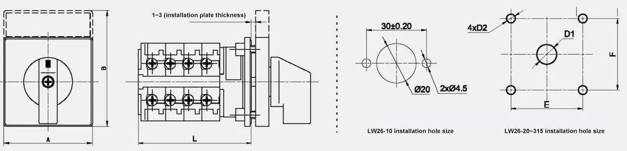
Lixin 3 Position On-off-On Rotary Cam Switch Overall dimensions and mounting dimensions:
Hot Tags: LW26 Series Rotary Switch, China, Manufacturer, Supplier, Factory, Wholesale, Customized, Cheap, Quality, Brands
Related Category
Send Inquiry
Please Feel free to give your inquiry in the form below. We will reply you in 24 hours.